Engineering
- Blast Protection System Design
- EMP/HEMP Protection System Design
- RF- Shielding Design
- Blast Calculation
Seismic Design:
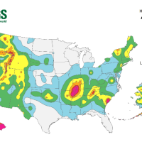
Provide tools for design and recommendations for analysis of structures against earthquakes. The new International Building Code incorporates more stringent design requirements for non-structural components, and buildings in compliance should show greater earthquake risk tolerance.
Designated seismic systems
The IBC identifies a limited class of MEP systems as “designated seismic systems.” These designated seismic systems comprise the equipment and their supporting utilities that are required to remain functional following a design earthquake to protect the safety of building occupants. This includes emergency power and lighting systems, fire suppression systems, and smoke exhaust systems associated with emergency egress paths. In addition to requirements for the attachment of these systems to the primary structure, the building code requires demonstration, by the equipment supplier, that the equipment will operate after experiencing design shaking.
The code recognizes three means of demonstrating that equipment is capable of post-earthquake operation: shake-table testing, which involves mounting a prototype on a table in a laboratory that shakes the equipment as if it were in an earthquake, followed by a demonstration that the equipment will operate; experience data, which consists of documented evidence that similar equipment experienced real earthquake shaking off at least the intensity of the design earthquake without failure; and suitable analytical evaluation. Most equipment is qualified by shake-table testing. Many manufacturers of pumps, compressors, motor control centers, switchgear, and other equipment have specially developed models of equipment that meet these requirements
Stress & Thermal Analysis:
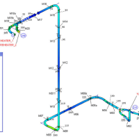
Pipe stress analysis is an analytical method to determine how a piping system behaves based on its material, pressure, temperature, fluid, and support. ... For instance, if it is a water system with no outside forces applied to the piping system, inspection or hand calculations are usually enough.
Simplified performed pipe-stress and displacement analyses using the latest Bentley AutoPIPE software and provided reports with recommendations on the required location and type of pipe supports needed to de-stress the piping system.
Simplify provides piping engineering services to the client:
3D modeled the steam and SIP piping systems as provided by the client.
Conducted several pipe-stress and displacement analyses of the client’s piping system.
Calculated the thermal movement, expansion, and displacement, and identified any locations of over-stressed pipe.
Provided reports for each system with recommendations on new types and locations of pipe supports to bring the stress’ to within allowable limits per ASME B31.3 code.
Surge Analysis:
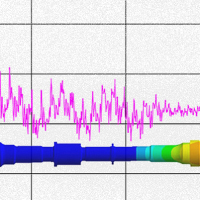
Anything that causes an immediate change in flow velocity, causes a pressure surge. This pressure surge is called a hydraulic transient.
A hydraulic transient (pressure and flow surge) continues until the system settles down to a new steady-state condition ( water flowing steadily or not). Problem transients or pressure surges are often caused by the starting and stopping of pumps, rapid valve closure, air entrainment, check valves, air valves, even surge anticipating valves, guide vane closure, and generator load rejection, turbine startup, and a myriad of other causes. Typical Surge Scenarios
A transient will typically propagate throughout a system. At a given position on a network, a variety of different transient pressures and velocities can superimpose causing more extreme events.
Common worst-case scenarios for surge analysis include:
Power Failure at maximum flow
Startup on a partially deprived system
valve closure/opening
burst control
valve failure
load rejection
plant shutdown/startup
priming
pump switch over
Provide tools for design and recommendations for analysis of structures against earthquakes. The new International Building Code incorporates more stringent design requirements for non-structural components, and buildings in compliance should show greater earthquake risk tolerance.
Designated seismic systems
The IBC identifies a limited class of MEP systems as “designated seismic systems.” These designated seismic systems comprise the equipment and their supporting utilities that are required to remain functional following a design earthquake to protect the safety of building occupants. This includes emergency power and lighting systems, fire suppression systems, and smoke exhaust systems associated with emergency egress paths. In addition to requirements for the attachment of these systems to the primary structure, the building code requires demonstration, by the equipment supplier, that the equipment will operate after experiencing design shaking.
The code recognizes three means of demonstrating that equipment is capable of post-earthquake operation: shake-table testing, which involves mounting a prototype on a table in a laboratory that shakes the equipment as if it were in an earthquake, followed by a demonstration that the equipment will operate; experience data, which consists of documented evidence that similar equipment experienced real earthquake shaking off at least the intensity of the design earthquake without failure; and suitable analytical evaluation. Most equipment is qualified by shake-table testing. Many manufacturers of pumps, compressors, motor control centers, switchgear, and other equipment have specially developed models of equipment that meet these requirements
Stress & Thermal Analysis:
Pipe stress analysis is an analytical method to determine how a piping system behaves based on its material, pressure, temperature, fluid, and support. ... For instance, if it is a water system with no outside forces applied to the piping system, inspection or hand calculations are usually enough.
Simplified performed pipe-stress and displacement analyses using the latest Bentley AutoPIPE software and provided reports with recommendations on the required location and type of pipe supports needed to de-stress the piping system.
Simplify provides piping engineering services to the client:
3D modeled the steam and SIP piping systems as provided by the client.
Conducted several pipe-stress and displacement analyses of the client’s piping system.
Calculated the thermal movement, expansion, and displacement, and identified any locations of over-stressed pipe.
Provided reports for each system with recommendations on new types and locations of pipe supports to bring the stress’ to within allowable limits per ASME B31.3 code.
Surge Analysis:
Anything that causes an immediate change in flow velocity, causes a pressure surge. This pressure surge is called a hydraulic transient.
A hydraulic transient (pressure and flow surge) continues until the system settles down to a new steady-state condition ( water flowing steadily or not). Problem transients or pressure surges are often caused by the starting and stopping of pumps, rapid valve closure, air entrainment, check valves, air valves, even surge anticipating valves, guide vane closure, and generator load rejection, turbine startup, and a myriad of other causes. Typical Surge Scenarios
A transient will typically propagate throughout a system. At a given position on a network, a variety of different transient pressures and velocities can superimpose causing more extreme events.
Common worst-case scenarios for surge analysis include:
Power Failure at maximum flow
Startup on a partially deprived system
valve closure/opening
burst control
valve failure
load rejection
plant shutdown/startup
priming
pump switch over